Odometer: 1311 mi
Task:
- OPMID install
- USB install
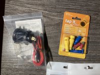
- SAE connector to battery install
Tools:
- JIS #1 screwdriver
- 5mm hex key
- 10mm socket
- Electrical tape
- Zip ties
OPMID install:
SAE cable install:
USB install:
Videos:
Best of the Backroads - Installing a USB and battery tender cable
OPMID - Honda Trail 125 - How to install on a Trail 125
Common parts:
RIVET, PUSH (6MM) - P/N 90116-K0A-E11
Total time: ~6h
These three were done at the same time since they require pulling most of the panels off to do the necessary work. Since this was a big job, it was very hot where I was working, and there are two good videos that cover 99% of this the photos and notes will be a little more sparse and utilizing more of the OEM fiche diagrams.
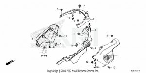
 Remove LID, BATTERY *R354* (GLOWING RED) (P/N 64460-K2E-T00ZB)
1. Push pin on the back left, 5mm hex key in the middle.
2. The back right of the panel has a small hook on it. Lift up from the left side, gently work things loose and then unhook it from the right rear.
Remove GARNISH SET, AIR CLEANER *R354* (WL) (GLOWING RED) (P/N 83650-K2E-A00ZA)
1. Push pin on the back top, 5mm on front middle. If you don't remove the battery cover first, take care when releasing the top left side of the panel, there's an easy to snap tab there.
Remove COVER SET, L. MAIN PIPE SIDE (TYPE1) (WL) (P/N 81140-K2E-T00ZC)
1. 5mm bolt lower front left, 5mm bolt center top, push pin center near the battery, 10mm socket for the flange bolt (P/N 95701-06012-00)
Reassembly note: The 5mm bolt on the lower front left is P/N 90132-KPP-T00, while the 5mm bolt in the center top is P/N 90132-MJE-D40 - these are different bolts, one has a longer shaft (longer shaft goes in to the top).
Remove COVER, MAIN PIPE (LOWER) (P/N 64310-K2E-T00)
1. 4x Push pins
Remove COVER (LOWER) *NHA40M* (MAT KRYPTON SILVER METALLIC) (P/N 64150-K2E-T00ZA) aka the bash plate.
1. 4x 5mm hex
Note: This wasn't strictly necessary, but it made accessing the oil temperature sensor easier and isn't very difficult to do.
Remove the front most screw from the front right body panel COVER SET, R. MAIN PIPE SIDE (TYPE1) (WL) (P/N 81130-K2E-T00ZC)
1. 5mm hex key.
Note: This wasn't strictly necessary, but it made verifying the OPMID tacho spade connector was securely pushed in much easier.
At this point, the main body covers are off, except the right side.
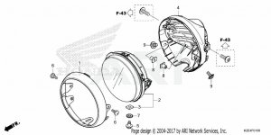
Remove RIM, HEADLIGHT (P/N 33101-K2E-T01) and HEADLIGHT UNIT (P/N 33110-K0F-T02)
1. This is part of the USB install but also used for the OPMID install. In the USB install video, the installer almost drops the headlight unit. Because of this, I taped it with some painter's tape first on the upper surface just in case, so if it did pop free it would just dangle from the tape.
2. Unscrew 2x screws on the 4 o'clock and 8 o'clock positions on the headlight. (P/N 91509-GE2-760) - JIS screwdriver
3. Release the headlight unit and unclip the plug at the back.
USB install: Follow the instructions from the video: Best of the Backroads - Installing a USB and battery tender cable
I ended up using a manual rasp because I only have a sanding wheel, and that sanding wheel attachment was going to die really fast on the soft aluminum mount. So I rasped it down most of the way, and then used the sanding wheel to clean it up to a nice finished surface. Of course, I still scratched up the aluminum mount in the process for the 10s I was using the dremel tool didn't I?
- Positap the black and yellow cable to the main headlight to your positive USB
- Positap the green cable to one of the blinkers to your negative USB.
Note: If doing the OPMID install, don't reassemble it yet, install the OPMID speedometer first, THEN reinstall the headlight.
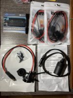
OPMID install: Follow the instructions from
OPMID - Honda Trail 125 - How to install on a Trail 125
-- WARNING --
BEFORE YOU START: record your odometer reading.
I also bought some OPMID screen protectors and installed them at the same time, because "right out of the box" is the cleanest this screen will ever be.
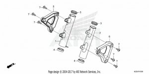
1. Remove the two screws holding the headlight unit to the left and right headlight brackets. (JIS screwdriver)
2. Inside there is a zip tie thing that's not exactly a zip tie holding all the cables bunched together. Check that your OPMID kit has a replacement for this before you cut it. Alternatively if you're creative with a knife, you can reuse it.
3. You can pass the screwdriver through the back of the headlight housing to access the screws on the instrumentation.
4. When installing the OPMID multimeter, the original speedometer used two washers on the left and right screws. The OPMID does not use those washers.
5. I couldn't reach the clip that holds the lowest point of the oil sensor cable without dropping the skidplate the first time. It's possible to reach it without doing that, but it's much easier to do it with the skidplate off.
It took me the longest time to figure out how to access the 1.4 menu for the odometer, etc. Ends up when you hold the A and B buttons together, if you hold them for 3s it does an adjust, and if you hold them for 6 seconds it enters the "bigger adjustment" mode (it will say ADJ at first, then FULL after 6s).
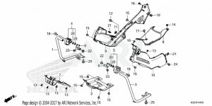
SAE cable install
I just could not get the right screws to do the battery work needed, so settled for a single SAE battery tender cable running backwards and reused the original screws. Due to the heat, I decided to run the quicker option of up under the seat instead of underneath the air box, which allows me to easily remove it if I don't like it for any reason..
1. JIS screwdriver for the battery terminals.
2. Redid the ring wire connectors to the correct size using my wire strippers, then installed it.
Because the fuel tank itself is exposed, there's no real way to hide the cable coming up from the battery to where the seat is. The best you can do is run it up the back and underside, which required a lot more work than I was willing to do in the moment. With a longer cable than the one I had it might be possible to follow the airbox up and pop it out near the snorkel which would be my second choice.
A single push pin on the front left of the gas tank area needed to be popped to work the cable under the body panel. The SAE fuse box sits in a little gap that's not quite big enough for sliding it in discretely; if you elect not to use a fused connection you will trade this problem for a different kind of problem. This is a less than ideal install location, but is easy to iterate on later.
End result:


Reference diagrams attached for the parts that I was generally fiddling with.
#2425Maintenance


")


.jpg")