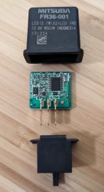
The Honda CT125 doesn't come with hazard lights / four-way flashers / park-anywhere lights and that's a feature I find myself wanting to make use of on occasion for temporary parking or for extra visibility.
* Check your local laws before using hazard lights. In many states there are few situations where it's legal to use hazards while a vehicle is in motion.
The kit I went with for this is: KITACO L-handle Switch, Part No.: 756-1470100
This kit is plug-and-play in terms of electrical wiring, but does require drilling a hole in the handlebar for aligning the switch assembly. The left and right handle switch assemblies each have an alignment peg on the inside of them that keeps their position fixed to a hole drilled on each side of the handlebar. The aftermarket switch assembly has that mounting peg at a different position where it doesn't line up with the hole in the OEM handlebar, so a new hole needs to be drilled.
Here's what came in the kit. Next to the plug end is a rectifier that Kitaco have added. It's labeled "MM8" and from what I can find seems to be a common Honda motorcycle electrical component with Honda P/N: 31700-MM8-610. Fit and finish on the switch assembly is nice and seems OEM quality. The wiring looks like they modified an existing product and then cleaned it up with electrical tape on both ends, but it looks like they did a good job of it and the wrapping is tight with no peeling.
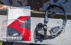
Kitaco provide both Japanese and English instructions as PDF downloads on their website. A drill template was included, but I misplaced it so I followed the instructions for using Adobe Acrobat to print with the "actual size" scale printing option selected.
For the installation I followed along with this video for the most part:
The plug for the left switch assembly is accessible tucked to the inside of the left fork tube. The plug has a rubber boot on it that slides over a metal tab for cable management, so you will want to slide it off of that tab to have enough room to work with the cable. Once the cable is disconnected it can be fed upward where the plug just fits past the meter stay bracket. Take your time with feeding the cable up, but if you have trouble with it you could remove the headlight and then the left side headlight bracket to get better access to the plug.
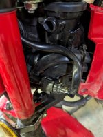
Remove the OEM left switch assembly by unscrewing the two Phillips screws from the back side of it.
My CT125 has Barkbuster hand guards installed and they were going to be in the way for drilling the handlebar so I partially removed the guard on the left side. If your CT125 has the stock bar end weights installed, Kitaco recommend removing the left side one so you don't drill into it.
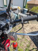
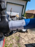
Drill template aligned over original hole and taped in place.
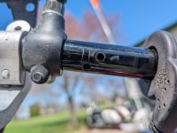
I used an automatic center punch to dimple where the new hole will be drilled in the handlebar, cleaned the hole with a deburring tool, and then ran a shop vac hose to the open bar end to try to remove the swarf.
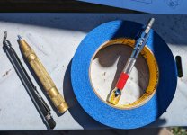
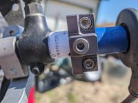
Some LSL handlebars I bought years ago included this drill jig for 7/8" or 22mm bars which I used. A jig isn't necessary but it makes it a lot harder to mess up. Without one just take your time, position the bar so you can get the right angle on it, use a punch, and drill a pilot hole. I looked up what it costs to buy just that LSL drill jig on its own today and it's not worth it especially with shipping, if you're looking to add a specialty tool to your collection there are cheaper AND more functional options that double as a saw guide.
Hardware stores in the USA often have a poor assortment of metric drill bits outside of tap sets, so if you don't have one on hand it might be easiest to buy a 5mm bit online. Or if you live near a Menards I've found that they're carried under the Menards' Performax brand. I didn't check a 3/16" to see if it would be too small or 13/64" if it would be too big, but if you have those on hand you could measure the alignment peg and find out.
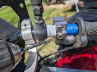
New alignment peg hole drilled and deburred.
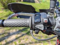
Kitaco left switch mounted. Note the added hazards button as well as the "PASS" option on the dimmer switch for all those times you'll be passing vehicles with less donkey power... or more likely just signaling a hazard to oncoming vehicles.
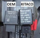
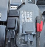
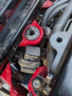
At this point I tested the hazards and the pass/high beam and everything worked. I don't know why Kitaco included the replacement turn signal relay, as it works without it. I contacted Kitaco to ask this question and will post an update here if they answer it. [Kitaco responded, reply in the comment after this post.] The hazard signal basically overrides the turn signal. By that I mean if you have a turn signal on and then turn on the hazards, the hazards take precedent and all four indicators will flash in unison. The turn signal cancel does not cancel the hazards, only pressing the hazard switch a second time will cancel them, and the turn signals will resume where you left them once the hazards are canceled, unless you canceled the turn signal while the hazards were on. When the hazards are on, the instrument cluster indicates it by blinking the turn signal indicator light on the display.
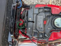
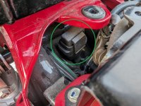
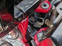
Continued in comment for turn signal relay replacement.
* Check your local laws before using hazard lights. In many states there are few situations where it's legal to use hazards while a vehicle is in motion.
The kit I went with for this is: KITACO L-handle Switch, Part No.: 756-1470100
This kit is plug-and-play in terms of electrical wiring, but does require drilling a hole in the handlebar for aligning the switch assembly. The left and right handle switch assemblies each have an alignment peg on the inside of them that keeps their position fixed to a hole drilled on each side of the handlebar. The aftermarket switch assembly has that mounting peg at a different position where it doesn't line up with the hole in the OEM handlebar, so a new hole needs to be drilled.
Here's what came in the kit. Next to the plug end is a rectifier that Kitaco have added. It's labeled "MM8" and from what I can find seems to be a common Honda motorcycle electrical component with Honda P/N: 31700-MM8-610. Fit and finish on the switch assembly is nice and seems OEM quality. The wiring looks like they modified an existing product and then cleaned it up with electrical tape on both ends, but it looks like they did a good job of it and the wrapping is tight with no peeling.

Kitaco provide both Japanese and English instructions as PDF downloads on their website. A drill template was included, but I misplaced it so I followed the instructions for using Adobe Acrobat to print with the "actual size" scale printing option selected.
For the installation I followed along with this video for the most part:
The plug for the left switch assembly is accessible tucked to the inside of the left fork tube. The plug has a rubber boot on it that slides over a metal tab for cable management, so you will want to slide it off of that tab to have enough room to work with the cable. Once the cable is disconnected it can be fed upward where the plug just fits past the meter stay bracket. Take your time with feeding the cable up, but if you have trouble with it you could remove the headlight and then the left side headlight bracket to get better access to the plug.

Remove the OEM left switch assembly by unscrewing the two Phillips screws from the back side of it.
My CT125 has Barkbuster hand guards installed and they were going to be in the way for drilling the handlebar so I partially removed the guard on the left side. If your CT125 has the stock bar end weights installed, Kitaco recommend removing the left side one so you don't drill into it.

Drill template aligned over original hole and taped in place.

I used an automatic center punch to dimple where the new hole will be drilled in the handlebar, cleaned the hole with a deburring tool, and then ran a shop vac hose to the open bar end to try to remove the swarf.

Some LSL handlebars I bought years ago included this drill jig for 7/8" or 22mm bars which I used. A jig isn't necessary but it makes it a lot harder to mess up. Without one just take your time, position the bar so you can get the right angle on it, use a punch, and drill a pilot hole. I looked up what it costs to buy just that LSL drill jig on its own today and it's not worth it especially with shipping, if you're looking to add a specialty tool to your collection there are cheaper AND more functional options that double as a saw guide.

Hardware stores in the USA often have a poor assortment of metric drill bits outside of tap sets, so if you don't have one on hand it might be easiest to buy a 5mm bit online. Or if you live near a Menards I've found that they're carried under the Menards' Performax brand. I didn't check a 3/16" to see if it would be too small or 13/64" if it would be too big, but if you have those on hand you could measure the alignment peg and find out.

New alignment peg hole drilled and deburred.

Kitaco left switch mounted. Note the added hazards button as well as the "PASS" option on the dimmer switch for all those times you'll be passing vehicles with less donkey power... or more likely just signaling a hazard to oncoming vehicles.

At this point I tested the hazards and the pass/high beam and everything worked. I don't know why Kitaco included the replacement turn signal relay, as it works without it. I contacted Kitaco to ask this question and will post an update here if they answer it. [Kitaco responded, reply in the comment after this post.] The hazard signal basically overrides the turn signal. By that I mean if you have a turn signal on and then turn on the hazards, the hazards take precedent and all four indicators will flash in unison. The turn signal cancel does not cancel the hazards, only pressing the hazard switch a second time will cancel them, and the turn signals will resume where you left them once the hazards are canceled, unless you canceled the turn signal while the hazards were on. When the hazards are on, the instrument cluster indicates it by blinking the turn signal indicator light on the display.
Continued in comment for turn signal relay replacement.
Last edited:

