op46
Active member
So had a good day and installed all remaining mods on one of the two LRDs, (536) today. With breaks it took 6 hours and only one minor tiny skint knuckle. First did the OPMID speedo install. Pretty straight forward after watching a few videos and following the paper instructions. Biggest thing is getting the red access covers off left side having never done it before. There are three types of fasteners and not all of them are the same in the types so keep up with what type came out of what hole. There are hex headed bolts (not all same) for those that are visible and metric 10mm bolts for the one hidden one under the CT125 logo air filter cover. The rest are these little plastic push pop rivets (need to find a source of supply for them), I didn't loose any but they are fragile and have two pieces that could be lost very easily.
I started forward and found I had to 1st take the battery access cover off with its one hex bolt and two pop rivets. Watch out for the hook it has on the right rear that goes under the cover under the exhaust pipe. I found out that its best to wiggle all covers and see where its tight and look to see if there is a pop rivet, hook, or lip holding removal down. Then I took the CT125 logo'd cover on the air cleaner off. Next the forward bar cover to the front wheel and handle bars. Finally the little black hidden pop riveted cover under the two front covers over the engine. Its held on by 5 or so of the pop rivets. (see pic).
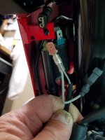
Unpacking the OPMID you got the speedo with cable attached, a substitution cable assembly and some zip ties. I started with the temp sensor substitution plug replacement and worked my way up the engine left side following the written instructions. Pretty straight forward until you get to the Y cable wire that goes to the coil pink and green wire spade connector under the right side forward cover. I didn't take that cover off and had a hell of a time getting to the spade connector which is on the bottom right of the engine support bar under the right forward cover about half way up. You put the sub cable Y branch on the green coil spade connector after removing the old wires spade connector and then hook the old one up to another floating spade on the sub cable Y branch for the coil. When I finally got it on it was loose and I had to take off and bend a little to tighten up the female sub Y connector to the coil green spade connector.
I then stowed the excess wire length and the old temp sensor plug wire, under the left side behind the air cleaner tube, which I did not take off even though the instructions say to. You clip the old temp sensor connector to a sub cable branch connector after putting the substitution cable temp sensor plug in its place on the bottom of the engine. Then you connect the little square 4 wire white connector on the sub cable to the OPMID end connector coming from it and lash down about half way down the engine support bar.
You mount the OMPID speedo in place of the HONDA one. Only one black screw removal is required to get bottom cover from the HONDA speedo, and once you pop it off downwards. Under the shell on the bottom of the HONDA speedo there are two sliver screws with washers holding the speedo on the steering yoke bracket. You will reuse all three of these screws but not the washers. You then put the OPMID into the bracket thru the two rubber bushings and snap the old gray HONDA speedo multi wire square connector into it. That's it other than putting the back shell of the OPMID on using the three screws you saved from the HONDA speedo. I put some small lock washers under those three screws to keep them from backing out. All that is left is programming the OPMID. It has two modes, a partial and complete program mode. You use the complete one to put in the unique CT125 setting for front, rear sprocket, rear tire and voltage. I also changed oil temp reading profile to the P-P2 from default and the temperate setting from degree C to Fahrenheit and the speed from KM to MPH. Set the clock and put in the 15 miles I had accumulated on the bike already into odometer total mileage setting.
Then on to the ignition switched DIN connector install using the headlight black and yellow for positive DC and the left turn signal green wire for negative using blue Posi-taps. Took longer to to heat shrink the DIN connector wire harness and spade connectors to try and make water proof as possible then the install.
Lastly was the handle bar risers and bar yoke rotation forward. Again pretty straight forward. Loosen the bottom nuts of the forward bar bolts and then remove the four bolts holding the bars. Spin the lower bar receptacle and put in the risers, put bar and top plate back on and install longer bolts that come with the risers. Tighten-up the lower nuts and then the four upper bolts and you done. See pictures below. Good videos available
too made by those who have gone before us.
COIL "Y" BRANCH FROM SUB CABLE OF OPMID and COIL GREEN SPADE CONNECTOR
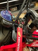
DIN DC RECEPTACLE INSTALL with TWO BLUE POSI-TAPs ON BLACK/YELLOW (+) AND GREEN WIRE (-) (Showing 11.3VDC on guage)
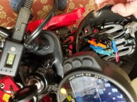
HANDEL BAR RISERs with YOKE ROTATION FORWARD and OPMID in PRESTART MODE (Clock showing 7:06PM and the 15 miles I programmed in)
I started forward and found I had to 1st take the battery access cover off with its one hex bolt and two pop rivets. Watch out for the hook it has on the right rear that goes under the cover under the exhaust pipe. I found out that its best to wiggle all covers and see where its tight and look to see if there is a pop rivet, hook, or lip holding removal down. Then I took the CT125 logo'd cover on the air cleaner off. Next the forward bar cover to the front wheel and handle bars. Finally the little black hidden pop riveted cover under the two front covers over the engine. Its held on by 5 or so of the pop rivets. (see pic).
Unpacking the OPMID you got the speedo with cable attached, a substitution cable assembly and some zip ties. I started with the temp sensor substitution plug replacement and worked my way up the engine left side following the written instructions. Pretty straight forward until you get to the Y cable wire that goes to the coil pink and green wire spade connector under the right side forward cover. I didn't take that cover off and had a hell of a time getting to the spade connector which is on the bottom right of the engine support bar under the right forward cover about half way up. You put the sub cable Y branch on the green coil spade connector after removing the old wires spade connector and then hook the old one up to another floating spade on the sub cable Y branch for the coil. When I finally got it on it was loose and I had to take off and bend a little to tighten up the female sub Y connector to the coil green spade connector.
I then stowed the excess wire length and the old temp sensor plug wire, under the left side behind the air cleaner tube, which I did not take off even though the instructions say to. You clip the old temp sensor connector to a sub cable branch connector after putting the substitution cable temp sensor plug in its place on the bottom of the engine. Then you connect the little square 4 wire white connector on the sub cable to the OPMID end connector coming from it and lash down about half way down the engine support bar.
You mount the OMPID speedo in place of the HONDA one. Only one black screw removal is required to get bottom cover from the HONDA speedo, and once you pop it off downwards. Under the shell on the bottom of the HONDA speedo there are two sliver screws with washers holding the speedo on the steering yoke bracket. You will reuse all three of these screws but not the washers. You then put the OPMID into the bracket thru the two rubber bushings and snap the old gray HONDA speedo multi wire square connector into it. That's it other than putting the back shell of the OPMID on using the three screws you saved from the HONDA speedo. I put some small lock washers under those three screws to keep them from backing out. All that is left is programming the OPMID. It has two modes, a partial and complete program mode. You use the complete one to put in the unique CT125 setting for front, rear sprocket, rear tire and voltage. I also changed oil temp reading profile to the P-P2 from default and the temperate setting from degree C to Fahrenheit and the speed from KM to MPH. Set the clock and put in the 15 miles I had accumulated on the bike already into odometer total mileage setting.
Then on to the ignition switched DIN connector install using the headlight black and yellow for positive DC and the left turn signal green wire for negative using blue Posi-taps. Took longer to to heat shrink the DIN connector wire harness and spade connectors to try and make water proof as possible then the install.
Lastly was the handle bar risers and bar yoke rotation forward. Again pretty straight forward. Loosen the bottom nuts of the forward bar bolts and then remove the four bolts holding the bars. Spin the lower bar receptacle and put in the risers, put bar and top plate back on and install longer bolts that come with the risers. Tighten-up the lower nuts and then the four upper bolts and you done. See pictures below. Good videos available
too made by those who have gone before us.
COIL "Y" BRANCH FROM SUB CABLE OF OPMID and COIL GREEN SPADE CONNECTOR

DIN DC RECEPTACLE INSTALL with TWO BLUE POSI-TAPs ON BLACK/YELLOW (+) AND GREEN WIRE (-) (Showing 11.3VDC on guage)

HANDEL BAR RISERs with YOKE ROTATION FORWARD and OPMID in PRESTART MODE (Clock showing 7:06PM and the 15 miles I programmed in)

Last edited:

